


Steam-in-Place (SIP): Preventing Temperature Validation Alarms
Application: Steam-in-Place (SIP) Sterilization, Biopharmaceutical Process Equipment, Clean Steam Condensate Removal
Media: Clean Steam (Pure Steam), Clean Steam Condensate, Sterile Air or Nitrogen
Valve Requirement: Pressure Reducing Valves (PRV), Sanitary Ball Valves, Clean Steam Traps
Steam-in-Place is one of the most critical—and unforgiving—steps in biopharmaceutical processing. During SIP, clean steam is circulated through process piping and equipment to sterilize every product-contact surface.
The challenge is not simply getting steam into the system. The entire process must reach and maintain the validated sterilization temperature. Condensate that backs up into a temperature sensor can cool the sensor just enough to trigger a validation alarm, stopping the SIP cycle and requiring the cause to be investigated before sterilization can begin again. Understanding how clean steam pressure, condensate removal, steam traps and drain piping work together can help prevent these costly interruptions.
What Is Steam-in-Place?
Steam-in-Place, or SIP, is a timed sterilization process used throughout upstream and downstream biopharmaceutical production.
After Clean-in-Place (CIP) and the final hot WFI rinse, clean steam produced from USP Purified Water is introduced into process tubing, vessels and other product-contact equipment. In large vessels, steam may enter through spray balls mounted within the vessel. SIP is a temperature-validated process. The system must reach a minimum sterilization temperature of 250°F (121°C) and maintain the validated temperature for the required sterilization period—commonly at least 30 minutes. If a monitored location falls below its validated temperature during the hold period, the system can generate a temperature validation fault. The SIP cycle must then be stopped, the cause investigated and corrected, and the sterilization cycle repeated.
The Three Phases of SIP
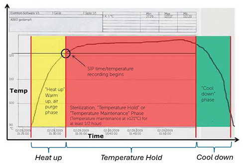
A typical SIP cycle occurs in three distinct phases.
1. Heat Up
An automated sanitary ball valve opens and allows clean steam to enter the process system. Before entering the equipment being sterilized, clean steam typically passes through a pressure reducing valve (PRV) that reduces distribution pressure to the pressure required to produce the desired sterilization temperature. A typical SIP pressure may be approximately 17–21 psig (1.17–1.45 barg), although the exact pressure is determined during system design. During Heat Up, steam raises the temperature of the piping, valves, vessels and other equipment until all monitored locations reach at least 121°C.
2. Temperature Hold
Once the required sterilization temperature has been reached throughout the system, the Temperature Hold phase begins. The system must remain at or above the validated temperature for the specified period. Even a small drop at a validation temperature sensor can trigger an alarm and invalidate the SIP cycle. This is where effective condensate removal becomes especially important.
3. Cool Down
After a successful Temperature Hold, the clean steam supply is shut off and condensate drains from the system. Sterile filtered compressed air—or nitrogen in some systems—is then introduced to help remove remaining moisture while cooling and drying the process piping.
Why Condensate Removal Is Critical to SIP Validation
Steam condenses as it transfers heat to cooler tubing and equipment. That condensate must be removed continuously and efficiently.
Validation temperature sensors, commonly RTDs, are typically installed near condensate outlets from process equipment. A common arrangement places the temperature sensor approximately 12–18 inches (300–450 mm) upstream of the clean steam trap.
The objective is straightforward:
Keep condensate from backing up high enough to reach and cool the temperature sensor. If condensate reaches the sensor during Temperature Hold, the measured temperature can fall below the validated limit—even though adequate clean steam may still be present elsewhere in the system. That small temperature change can result in a failed SIP cycle.
How Sanitary Thermostatic Steam Traps Work
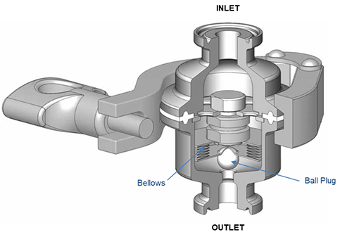
Balanced-port thermostatic steam traps operate much like a thermostat. Inside the trap, a bellows contains a proprietary liquid mixture. When the bellows is exposed to saturated clean steam temperature, the liquid vaporizes and expands the bellows. This drives the plug against the trap seat, preventing live steam from escaping. As condensate accumulates and cools below steam saturation temperature, the bellows contracts. The plug lifts from the seat and allows condensate to discharge. The temperature difference between steam saturation temperature and the temperature at which the trap begins to open is known as subcooling. For SIP applications, subcooling matters.
Lower Subcooling Means Faster Condensate Removal
A trap requiring significant subcooling allows condensate to cool—and accumulate—before the trap begins to open. The greater the condensate accumulation, the greater the possibility that it will rise through the drain leg and reach the validation temperature sensor. For validated SIP service, thermostatic steam traps offering approximately 3°F or less of subcooling are considered ideal because they begin discharging condensate closer to saturated steam temperature.
Four Common Causes of SIP Temperature Validation Alarms
Temperature alarms are not always caused by insufficient steam temperature. Frequently, the underlying problem is condensate management.
Four areas deserve particular attention.
1. Excessive Steam Trap Subcooling
If a thermostatic trap requires too much condensate cooling before opening, condensate can accumulate upstream of the trap. With the temperature sensor commonly positioned only 12–18 inches above the trap, backed-up condensate may reach the sensing element and lower its measured temperature enough to trigger a validation alarm. Selecting a sanitary steam trap with low subcooling helps minimize condensate accumulation.
2. Failure of an Adjacent Steam Trap
A failed trap can affect more than its own drain leg. Balanced-port thermostatic sanitary traps typically fail open if the bellows loses its internal fill. When this occurs, clean steam can pass through the failed trap into the common condensate collection header. The resulting increase in header pressure reduces the differential pressure across the other traps connected to the header:
Differential Pressure = Inlet Pressure – Outlet Pressure
As differential pressure decreases, the condensate-handling capacity of the remaining traps also decreases. Condensate can then begin backing up in an adjacent drain leg, eventually reaching its validation temperature sensor and causing an alarm. For this reason, traps should be tested individually during Temperature Hold when troubleshooting recurring validation faults.
3. Undersized Drain Tubing or Steam Traps
Proper trap and drain-leg sizing begins with the condensate load. The amount of condensate generated by the tubing and equipment being sterilized must be calculated before the drain tubing and steam trap can be properly sized. Small tubing can create particular problems. For example, an 18-inch section of ¾-inch tubing has approximately 2.8 times the internal volume of ½-inch tubing. For the same condensate load, liquid therefore rises much faster in the smaller drain leg. Larger tubing also provides greater external surface area for heat transfer—important because validated downcomers are commonly left uninsulated specifically to help cool the condensate before it reaches the trap. For many temperature-validated SIP drain legs, ¾-inch tubing is preferable to ½-inch tubing, depending on calculated condensate load and system design.
4. Undersized Condensate Collection Headers
The condensate header must handle the combined load from every steam trap connected to it. This becomes especially important during Heat Up, when condensate generation is at its highest. If the header is undersized, backpressure can increase throughout the condensate system. That reduces differential pressure across the traps, slows condensate drainage and increases the likelihood that condensate will back up toward one or more validation temperature sensors. A condensate collection header should therefore be sized for the combined worst-case condensate load during Heat Up and Temperature Hold, rather than simply matching the size of individual drain connections.
Designing SIP Systems for Reliable Temperature Validation
Successful SIP depends on more than supplying clean steam at the proper temperature.
The complete condensate-removal system must work together:
- Maintain the correct clean steam pressure and corresponding saturation temperature.
- Use low-subcooling sanitary steam traps.
- Size each trap for the calculated condensate load.
- Provide adequately sized temperature-validated drain legs.
- Size common condensate headers for the combined system load.
- Position temperature sensors and traps to minimize the possibility of condensate reaching the sensing element.
- Test individual traps when troubleshooting unexplained validation alarms.
A temperature validation alarm may appear to be a temperature problem. In many cases, however, the underlying issue is condensate that is not leaving the system quickly enough.
Talk to a Steriflow Application Engineer
Steriflow application engineers can help evaluate clean steam pressure, condensate loads, steam trap sizing and SIP condensate-removal requirements.