
What Factors Influence Offset and the Amount of That Offset?
Some factors are intrinsic to all regulator designs, but other factors can be controlled by regulator selection or option specification.
When working with pressure regulators, offset (droop) is an important performance characteristic to understand. Some factors influencing offset are intrinsic to all regulator designs and cannot be controlled by the user, while others can be managed by regulator selection, option specification, or commissioning practices.
Intrinsic Design Factors That Influence Offset
Some amount of droop is inherent in all regulator designs.
There are several physical forces acting on the Diaphragm, Spring and Plug as flow changes that cause offset. These forces can never be completely eliminated from any manufacturers design.
But…they can be influenced by a regulator manufacturer’s basic design, and are therefore under the control of the person that selects a particular regulator design, and it’s specific features or options.
For example: regulators with large diaphragm areas, a small amount of total stroke (distance the stem moves from full open to full close), and a properly selected spring relative to the set point, generally have less offset than those that don’t have those features.
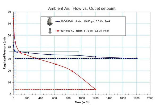
- Diaphragm area: The lines in the test chart (below) vividly illustrate the different in offset of two different regulators on the same application. The red line is the offset curve for a small, clean gas and air regulator’s diaphragm with about the same total stroke length and spring rate as the large diaphragm regulator that produced the blue offset curve. In this case, the different in offset performance primarily has to do with the diaphragm area different. The regulator photographs below give you a relative idea of the diaphragm area difference. It really makes a difference.
- Stroke Length: a regulator with a shorter total stroke will outperform a regulator with a longer stroke if all other factors are held constant.
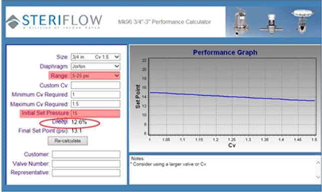
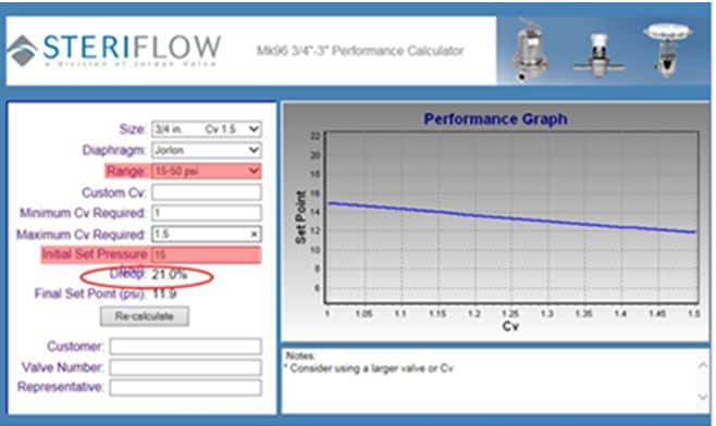
- Spring Rate or Compression at Set Point: selecting the right spring range for your specific regulator set point influences offset. Generally speaking, the more compressed the spring is at your set point pressure, the less offset exhibited. In other words, when selecting a spring range for your regulator, select a spring range that puts your set point closer to the upper end of the spring range. Look at the droop figures circled in the comparative graphs below for an example. A spring range of 5 to 25 psi is clearly a better spring choice for a 15 psi set point than the 15 to 50 psi range spring.
- Forces Acting on the Plug: Regulators with larger diaphragms are much less susceptible to the hydraulic and velocity forces acting on the plug. The force acting on the small plug of a large diaphragm regulator is insignificant relative to the force acting on that regulators diaphragm because of the relative area those forces are acting on. (Force = Pressure x Area). By contract, small clean air and gas style regulators have a much smaller diaphragm area relative to the plug. They are therefore more susceptible to forces acting on the plug. As a result they exhibit more offset.
Factors that the user can control during regulator commissioning to lower offset:
Set your regulator at flowing conditions! If you bench set a regulator in the shop at a low flow rate and install it on an installation with higher flow rates than your test bench, the regulator set point will droop lower at the higher flow rates. Set the pressure in your installation following these guidelines.
Applications with Stable Flow Rates
- Example: Stable clean compressed air and gas pressure control: for stable sparge, or continuous blanket gas flows, set the installed regulator at your normal flow rate. It will remain at that set point. Another benefit is that you don’t need a more expensive larger process type regulator. A small gas regulator will usually work fine and be accepted by most pharma E & C’s and end users. The only exception to that rule would be if the regulators set point is below 5 psi, as a larger diaphragm can help with set point stability at lower pressure settings.
- Example: Stable ambient WFI or USP purified water point of use pressure control: for pressure reduction for stable ambient WFI points of use (filling a formulation vessel with WFI for example), set the outlet set point at that filling flow rate. If you do, the pressure will not vary during filling. Note that for this particular application, your customers will usually require that you provide a process type regulator for drainability reasons.
Applications with Variable Flow Rates
Example: Clean steam for SIP pressure/temperature control: set the regulator with steam flowing at a mid to high flow rate to minimize the total variance in offset during operation. Look at the blue curve in the air flow offset chart below. If you set the regulator at 880 scfh, the maximum offset you will experience at your maximum flow of 1800 scfh (during heat up for example) is about 1.5 psi. The same is true when the flow decreases substantially during Temperature Hold.