
Valve Sizing Calculations and Optimization
How to Select the Right Valves for Liquids, Gases, and Steam Systems
Precise control of fluid flow is crucial for maintaining operational efficiency, ensuring safety, and controlling costs. Whether handling liquids, gases, or steam, selecting the correct valve size is a critical engineering decision that directly affects system performance.
Valve sizing calculations provide the foundation for this decision, ensuring control valves deliver the required flow rate while maintaining stable operation under changing process conditions.
Improper valve sizing can result in excessive pressure drop, poor controllability, noise, vibration, and premature equipment wear.
For engineers designing or optimizing liquid, gas, and steam systems, accurate control valve sizing is essential to achieving reliable and efficient operation.
This post examines the principles and practical application of valve sizing across different fluid services. It explains the role of the flow coefficient Cv, outlines the key factors that influence sizing decisions, highlights common calculation errors, and provides real-world examples for liquid, gas, and steam systems.
Understanding Flow Coefficient (Cv)
The flow coefficient Cv is the cornerstone of valve sizing calculations, providing a standardized measure of a valve’s flow capacity. Cv represents the number of U.S. gallons per minute of water at 60°F that will flow through a valve with a 1 psi pressure drop across it. This standardized capacity index allows engineers to compare valve performance across manufacturers and predict flow behaviour under specific operating conditions.
The term Kv is the metric equivalent of Cv. It is the standard for valve sizing in Europe and many other regions following IEC standards. Like Cv, it quantifies a valve’s capacity to pass fluid (liquid or gas). Kv specifically defines the flow rate in cubic meters per hour (m3/h) of water that will pass through a fully open valve with a pressure drop of 1 bar.
The Fundamental Cv and Kv Equation
- For liquid applications, the basic Cv (Kv) calculation follows this formula:
Cv = Q × √(SG / ΔP) (using Imperial units)
Kv = Q × √(SG / ΔP) (using Metric units)Where:
- Cv, Kv = Flow coefficient
- Q = Flow rate (gallons per minute, or cubic meters per hour)
- SG = Specific gravity of liquid (relative to water in either imperial or metric units)
- ΔP = Pressure drop across the valve (psi, or bar)
- For gas and vapor applications, the calculation becomes more complex due to compressibility effects. Engineers must account for the expansion factor (Y), gas specific gravity, temperature, and the critical pressure ratio. The gas service equation is:
Cv = Q × √(T × SG × Z) / (1360 × P₁ × Y × √(ΔP × (P₁ – ΔP/2)))
Factors Affecting Control Valve Sizing
Accurate regulator or control valve sizing calculations require careful consideration of multiple interrelated factors, as follows, that vary significantly between liquid, gas, and steam applications.
- Flow Rate Requirements: Determining the valve flow rate is the first step in sizing; it must encompass three critical operating points: normal, minimum, and maximum flow conditions. Engineers must size valves to handle not just typical operation but also startup, shutdown, and emergency scenarios. For liquid systems, flow rates are typically specified in GPM (gallons per minute) or m³/h. Gas and steam systems may use SCFM (standard cubic feet per minute), lb/h (pounds per hour), or other mass flow units depending on the application and regional standards.
- Pressure Drop Considerations: The pressure drop in valves represents the energy consumed by the flow control device. To calculate pressure drop, we need the minimum, normal and maximum valve inlet pressure and outlet pressure. For liquid applications, excessive pressure drop can induce flashing cavitation when the local pressure falls below the liquid’s vapor pressure as it passes through the valve orifice causing bubble formation. As pressure builds on the outlet side of the orifice, cavitation can occur. Cavitation is the subsequent violent collapse of those bubbles as the pressure increases. It can damage the valve trim and body especially in globe style valve. In other valve designs with lower pressure drop like Jordan Valve Sliding Gate design, if cavitation occurs, it will happen downstream of the valve, in which case a sacrificial spool piece can be inserted to absorb the impact.The cavitation index (σ) helps predict this phenomenon. Some sizing programs, like the
Jordan Valve/Steriflow Valve/LowFlow JVCV program, will automatically calculate the cavitation index, and integrate warnings in the sizing results, and reports.Gas and steam systems face different challenges. Pressure drop in compressible fluids is limited by choked flow conditions, which occur when the fluid velocity reaches sonic speed
at the valve’s vena contracta. Beyond this critical pressure ratio, further downstream pressure reduction does not increase the flow rate. Engineers must calculate the choked pressure drop and ensure the valve operates below this limit to maintain controllability. - Temperature Effects: Operating temperature affects fluid properties, including viscosity, density, and vapor pressure for liquids, and density and compressibility for gases. Steam temperature determines whether the service involves saturated or superheated steam, fundamentally changing the calculation approach. High-temperature services also impose material constraints, limiting available valve body and trim materials and requiring special consideration for thermal expansion effects on both the valve and the piping system.
- Flow Types (Regimes) – Turbulent Flow or Laminar Flow:
- Turbulent flow generally describes the characteristic of fast-moving, non-viscous fluids flowing through larger tubes or pipes. The chaotic nature of pressurized turbulent fluid passing through an orifice will create sound waves, disturbances, and pressure fluctuations leading to vibrations, generation of noise and cavitation.
- Laminar flow generally describes the flow of lower velocity fluids through smaller tubes or pipes, and more viscous flows in larger tubes or pipes. The more ordered nature of pressurized laminar flow moving through a valve orifice does
not exhibit these disturbances.
The Reynolds number (Re) is a dimensionless value in fluid mechanics that represents the ratio of inertial forces to viscous forces within a fluid. Fluid density, velocity,
viscosity, and internal inlet/outlet pipe diameter are needed to calculate it.Re predicts flow regimes (types), whether the flow is Laminar or Turbulent. A low Re indicates orderly laminar flow, while a high Re indicates more chaotic, turbulent flow.
As Laminar or Turbulent flow moves through a valve their flow characteristics persist. That is why it is very important to account for that when sizing. Some sizing programs will calculate the Reynolds number and tell you whether or not the fluid is likely to exhibit laminar flow and recommend direction to use an alternate sizing routine in the
program. It’s an important recommendation, as the ISA (International Society of Automation) developed different valve sizing equations for each flow scenario. Likewise, our engineers created two different methods of sizing in our JVCV sizing program.
Summary:
| Fluid Type | Primary Sizing Concern | Key Variable | Risk Factor |
| Liquids | Constant Density | Specific Gravity (SG)
Vapor Pressure (VP) |
Cavitation / Flashing |
| Gases | Compressibility | Critical Pressure Ratio | Choked Flow (Sonic) |
| Steam | Phase State (Dry/Wet) | Superheat/Saturation | Erosion / Wet Steam |
| Any | Flow type: (Turbulent or Laminar) | Reynolds number (Re) | Erroneous Sizing Results |
Common Mistakes to Avoid in Valve Sizing
Even experienced engineers can fall into sizing traps that compromise system performance and reliability. The following are some of the most common control valve sizing mistakes engineers should avoid:
- Ignoring Choked Flow Limits: For gas and steam applications, failing to check for choked flow conditions leads to valves that cannot deliver the expected flow rate. When the pressure drop exceeds the critical ratio (typically around 50% of absolute inlet pressure for many gases), increasing valve opening no longer increases flow. In these cases, the valve may appear undersized when in reality it is already operating at its physical flow limit.”
- Neglecting Cavitation and Flashing: Valves require cavitation analysis to prevent destructive erosion and noise. The cavitation index must be calculated and compared against the valve’s predicted cavitation behaviour (Kc factor). Similarly, engineers must verify that downstream pressure remains above the vapor pressure to prevent flashing, which can damage trim and drastically alter flow characteristics.
- Ignoring the Reynolds Number: Whether a fluid is Turbulent or Laminar affects a fluids movement through a valve. It must be calculated when sizing valves, or the results will be erroneous. That’s why it’s important to input internal piping diameters, and fluid density, velocity, and viscosity. Most sizing programs will know the physical properties of common fluids, but for non-common fluids, make sure you input those values.
- Using Incorrect Units: Mixing measurement systems (combining psi with bar, or GPM with m³/h without proper conversion) produces calculation errors that can result in valves that are off by factors of 2× or more. Always verify that all input parameters use consistent units before performing calculations.
- Forgetting Turndown Requirements: Sizing solely for maximum flow while ignoring minimum controllable flow results in poor performance during startup, batch operations, or low-load conditions. A valve must provide acceptable control authority across the entire operating range, not just at one design point.
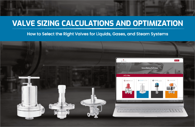
It’s important to know that our Control Valve and Regulator sizing program (JVCV) requires you to choose units from a dropdown menu, and to input minimum, normal and maximum flow and pressure conditions. It will also automatically calculate for Choked Flow, Cavitation, Reynolds number, and tell you by calculating “% open”, and providing guidelines as what the valves turndown capabilities are. That goes a long way to minimizing the above common sizing mistakes.
Mastering valve sizing calculations is fundamental to designing efficient, reliable fluid handling systems. Ready to optimize your liquid, gas, or steam system with precision-engineered sanitary valves? Jordan Valve, Steriflow Valve and Low Flow valve offer industry-leading control valves, and regulators designed for accurate flow control across demanding applications. Whether you’re working in industrial manufacturing, food and beverage processing, pharmaceuticals or biotechnology, and are not sure which calculation applies to your specific media. Contact a Steriflow engineer today for a custom valve sizing consultation.