Special SIP Applications for Large Vessels
How Process Design Engineers have traditionally designed the outlet tubing of large vessels to accommodate clean steam sterilization.
Biopharm International addressed the subject of vessel steam sterilization and vessel steam in place (SIP) tubing design in an article published in 2006. It’s the first article that I know of that addressed the amount of clean steam required to heat up and hold various sizes of process vessels at sterilization temperature.
- A 40,000 biopharmaceutical vessel will product about 2500 lbs/hr (1134 kg/hr) of peak condensate during heat-up and approximately 27 lbs/hr (0,91 kg/hr) during Temperature Hold.
- By contact, a 600 L vessel will only produce about 100 lbs/hr (45,36 kg/hr) of peak condensate during heat-up, and approximately 2 lbs/hr (0,91 kg/hr) during Temperature Hold.
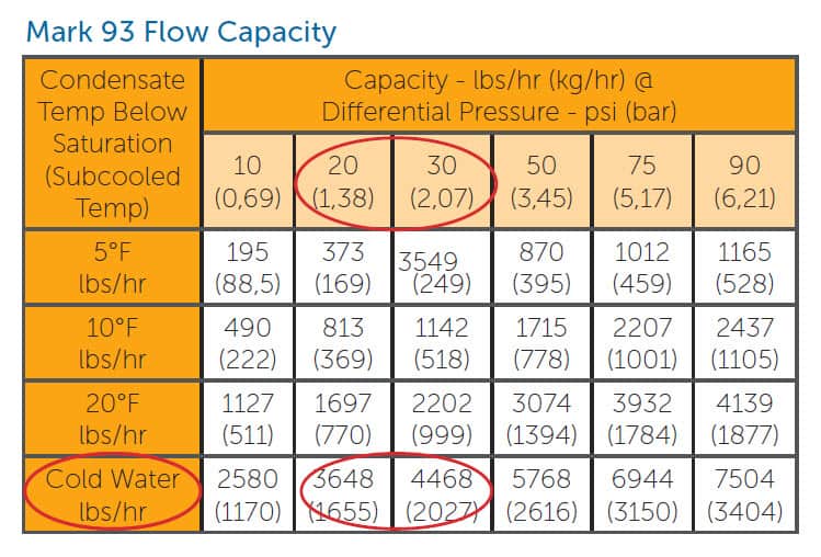
While 2500 lbs/hr (1134 kg/hr) is within the capacity capabilities of most standard steam traps (at normal SIP differential pressures), those traps can only handle that load at very high levels of subcooling (see Mark 93 Capacity Chart below). That means the condensate has to be subcooled to the point where the trap bellows is completely contracted before the trap can handle the load. In other words, the condensate will significantly back up before it cools enough to fully contract the bellows and allow full flow.
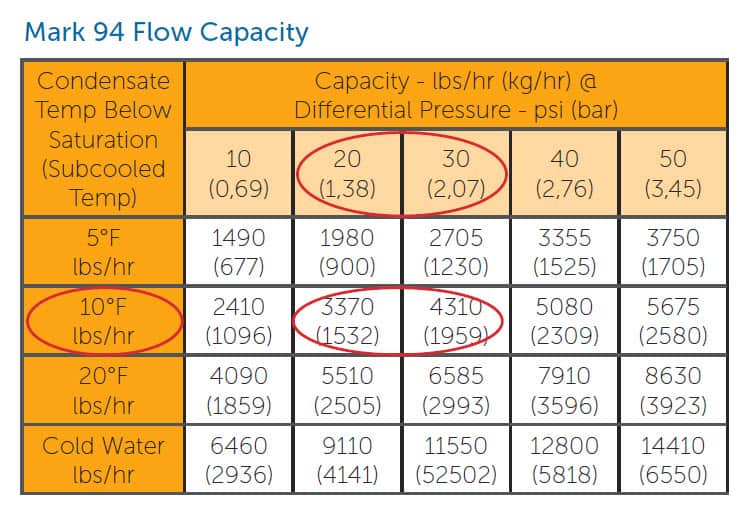
Most high capacity traps can handle large vessel heat-up loads at lower levels of subcooling. See Mark 94 Capacity Chart below, but they still drain slowly, requiring about 10°F subcooling.
Removing condensate efficiently from vessels during SIP is important, but it is not the only job that a trap has to do. Clean Steam Traps also have to handle the large volume of air that will be displaced at the beginning of SIP.
A 15,000L biopharmaceutical vessel holds 15,000L of air. As a general design rule, air should be removed in the first 5 minutes of SIP in order to minimize heat-up time (air acts as an insulator in steam tubing and vessels). Moving 15,000L of air in 5 minutes represents a flow rate of 30000N L/min. Plugging that into a Cv calculator with a 25 psi differential, we find we need a trap with a Cv of 4.9 in order to move that much air through the trap. The Mark 93 Series, a mid-capacity trap that has a Cv of 3,8, will only remove about 2300 N L/minute, or about 11,500 liters of air in 5 minutes. Even the higher capacity Mark 94 Series with a Cv of 4.0 can’t completely handle that quantity of air in a timely manner.
Lastly, during heat-up, air and condensate do not drain independent of each other. Both combine in a mixed phase flow which further complicates draining.
In order to drain liquids and expedite air and condensate flow out of larger vessels (usually ≥ 600L), most process designers include a ≥ 1″ primary bypass from the tank outlet – harvest line. When heat-up is complete (when temperature hold starts), a second 3 way bypass diverts the flow from the bypass drain through a conventional steam trap and back to drain.
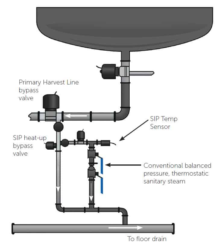
Heat-up:
During SIP heat-up, air and condensate are diverted through the harvest line 3-way bypass valve directly to drain.
Temperature Maintenance:
When the SIP temperature sensor reaches ~ 203°F (95°C), the bypass valve opens to direct the lighter condensate load through the steam trap. Actual temperature depends upon DCS/PLC configuration.
Note: During Sanitization (pre SIP), Rinse and CIP, liquids are usually diverted through the primary harvest line 3-way bypass valve directly to drain. Although some end users divert through a secondary harvest line 3-way bypass valve further downstream.
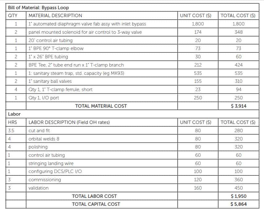
While this piping arrangement effectively handles fluids, air and condensate, there are 2 problems associated with conventional bypass loops:
- Inefficient use of clean steam slow pressure build up because of live steam loss), resulting in longer SIP heat-up times and higher operating expense.
– During the typical 10 – 15 minutes of heat-up, the ≤ 1″ bypass is wide open to drain, resulting in slow pressure build-up. After the initial expulsion of air, a significant amount of clean steam is lost to drain before temperature hold, resulting in longer than required heat-ups and higher operating costs. - High initial capital cost
– a conventional bypass loop consists of components and labor. It conservatively costs about $5800 US.